
Foreword
This standard was formulated for the first time according to the needs of the development of my country's stage lighting industry.
The symbol part of this standard refers to the stage lighting fixture symbol recommended by the International Commission on Lighting (CIE).
This standard refers to the recommended technical document "Common Terminology and Symbols for Stage Lighting" published by the Beijing Lighting Society; Designed by the Shanghai Theater Academy, "Drawing Template for Stage Lighting Fixtures" produced by the Zhejiang Institute of Stage Electronics Technology, and English, American, and Japanese Relevant symbols of other countries.
The State Technical Supervision Bureau has recently released GB/T1.1-1993 "Guidelines for Standardization Work Unit 1; Standard Drafting and Expression Rules, Part 1: Basic Provisions for Standard Preparation", which sets new requirements for the preparation of standards , This standard is prepared according to the new regulations.
This standard will be implemented from October 1, 1995.
Appendix A, Appendix B, and Appendix C of this standard are all standard appendices.
This standard is proposed by the Science and Technology Department of the Ministry of Culture and is under the jurisdiction of the Ministry of Culture.
This standard is drafted by: Shanghai Stage Technology Research Institute; participating drafting units: Shanghai Guangyao Film and Photographic Equipment Factory, Handan Lighting Factory.
The main drafters of this standard: Shi Weicang, Tian Fang, Li Guoliang, Zhao Qinglan.
1 Scope
1.1 This standard stipulates the basic rules of graphics, symbols, codes, and drawing of light positions and lighting patterns used in stage lighting design.
1.2 This standard is applicable to the light position diagrams and light layout drawings drawn by lighting designers to express their design intent. The graphic symbol part also applies to the identification mark of the product packaging of the lamp manufacturer.
1.3 The light position diagrams, light layout diagrams and related terms in this standard are mainly used for the frame-type stage. Other forms of stage and occasions with similar functions to the stage lighting design are used for reference.
2 Reference standards
GB4457—84 mechanical drawing
GB7093.1—7093.4—86 Graphic symbol representation rules
GB/T14076-93 General technical requirements for film and television stage lamps
JGJ57—88 Theater Building Design Code
3 Definition
3.1 Picture frame stage
Use a frame-shaped stage at the front of the performance area.
3.2 Light map
It indicates the installation position of stage lamps (hereinafter referred to as lamps), and shows the diagrams of lamp types, performance and accessories.
3.3 Lighting pattern
Diagram showing the projection position, projection range and color change of the light beam of the lamp.
3.4 Taikou Line
It is represented by a thin dash-dotted line along a horizontal axis that is dummy inside the stage building entrance. (see picture 1)
3.5 Central axis
A dummy axis extending from the center point of the Taikou line to the center point at the rear of the stage is indicated by a thin dashed line. (see picture 1)
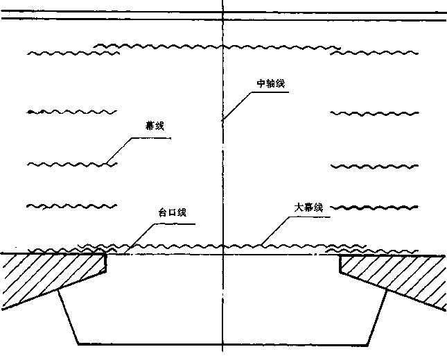
Figure 1
3.6 Big curtain line
The projection line of the big screen on the stage plane is represented by a wavy line. (see picture 1)
3.7 Curtain line
The projection line of the curtain on the stage surface is represented by stray lines. (see picture 1)
3.8 Stage orientation
Take the actors standing on the stage and facing the audience as the left and right orientation of the stage (the left side is also called the next door, the right side is also called the upper door).
3.9 Contour
In the diagram, connect the lamps with the same height with a thin solid line, and mark the height. This line is called the contour line. (See Figure 8)
3.10 Name of lamp position
In the frame stage, the following names are commonly used for the location of the lamp installation.
3.10.1 Frontal light (also called surface light)
The light position located outside the stage entrance and projecting from the top to the stage is called the first front light by the stage entrance, in order of two front lights and three front lights...
3.10.2 Outside light of the mouth (also known as slap, outside light)
A light position located on the side wall of the auditorium and projecting light from both sides of the stage entrance to the stage. According to the provisions of 3.8, the left and right sides are divided. When there are more than two channels of outside light, they are divided into one, two, and three channels in the order specified in 3.10.1.
3.10.3 Inner side light (also called column light, false side light)
The light positions located on both sides inside the stage entrance, near the stage frame, are generally set on the side panels of the pillar lamp holder or fake stage entrance, and are divided into left and right according to the provisions of 3.8.
3.10.4 Side light (also called inside light, flyover light)
The light positions on both sides of the stage are divided into left and right according to the provisions of 3.8. When there are multiple side lights on the same side, they are called one side light, two side lights, and three side lights in order from bottom to top.
3.10.5 Footlight
A light position that is located on the front of the stage lip and casts light from the stage.
3.10.6 Ceiling light
The light positions at the top of the stage are called one top light, two top lights, and three top lights in the order from the stage entrance to the rear of the stage. 3.10.7 Top light outside the platform
Located on the top outside the stage entrance, the light position between the front light and the stage entrance.
3.10.8 Skylight
A lamp position that is located at the front or rear of the sky screen to project light to the sky screen.
3.10.9 Flowing light
The lamp position can be moved on the table.
3.11 Lamp name
Apply the name in GB/T14076 and related luminaire standards.
3.12 Name of stage parts
Apply the relevant part of JGJ57 noun explanation (see Appendix C).
4 Symbol
When drawing diagrams, the following prescribed symbols shall be used.
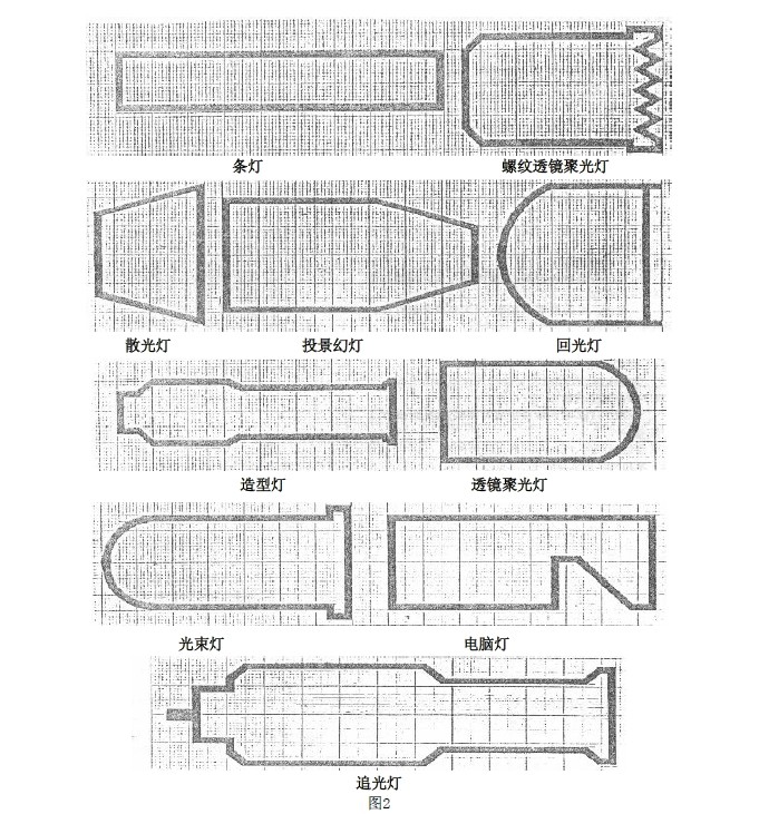
4.1 Symbols of commonly used lamps. (See Figure 2)
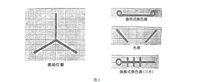
4.2 Symbols for accessories of commonly used lamps and lanterns. (See Figure 3)
5 Technical drawing
5.1 Drawing format and format The relevant provisions of GB4457.1 shall apply to the drawing format and format, see Appendix A for details. The title bar is located in the lower right corner of the picture frame, and its dimensions and contents are drawn as shown in Figure 4.
5.2 Form and application of graph
5.2.1 The relevant regulations of GB4457.4 shall apply to the name, type, code and width of various diagrams. For general application on the diagram, see Table 1.
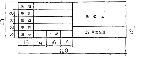
Figure 4

5.3 Font
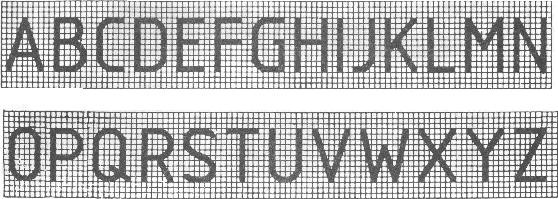
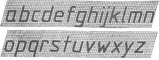
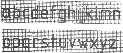
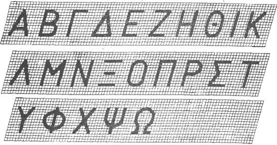
The relevant regulations in GB4457 shall apply. (See Annex B)
5.4 Light map
The light position diagrams are all expressed in the form of an approximate plan, and no elevation is required without special needs.
The light map should be able to represent the following:
a. The location and height of the lamp installation.
b. The type, model, voltage, power and additional parts of the lamp.
c. The number of the luminaire.
5.4.1 Representation of lamp position
5.4.1.1 Baseline
The central axis, the platform line, the large curtain line, the curtain line and the installation position of the scene in the light position map should be drawn and dimensioned in proportion, the unit is meter, accurate to two decimal places. (See Figure 7)
5.4.1.2 Representation of plane position
The plane position of the lamp is subject to the position of the lamp symbol. The size of the symbol has nothing to do with the actual ratio of the lamp, but it should be proportional to the proportion of the picture frame. The size of the same symbol in the same picture frame should be consistent.
5.4.1.3. Representation of lamp height
Since the three-dimensional lamp position is displayed on the plan view, the phenomenon that the upper and lower lamp positions overlap on the drawing position may occur. Therefore, the following expression rules are specified. (See Figure 7)
a. The light positions on the left and right sides of the stage are based on the central axis, the lower part is near the central axis, and the upper part is away from the central axis. The position of the lights inside and outside the stage entrance is based on the table entrance line, the lower part is close to the table entrance line, and the upper part is away from the table entrance line.
b. The common three-dimensional light positions of the stage (such as the outside light of the stage entrance and the inside light of the stage entrance) are generally fixed in height, and can not be marked in the picture. The lamp positions that are easily confused with the plane lamp positions must be marked with height. Use the symbol in Figure 5 to indicate the plane position of the upper lamp position, and use the symbol in Figure 6 to indicate the height. When the arrow points to a single lamp, it indicates the height of the lower part of the lamp. When the arrow points to the contour line, it indicates the group of lamps. Height (based on the lower part of the lowest lamp). The unit is meter, accurate to two decimal places. (See lights 81-84 in Figure 8)
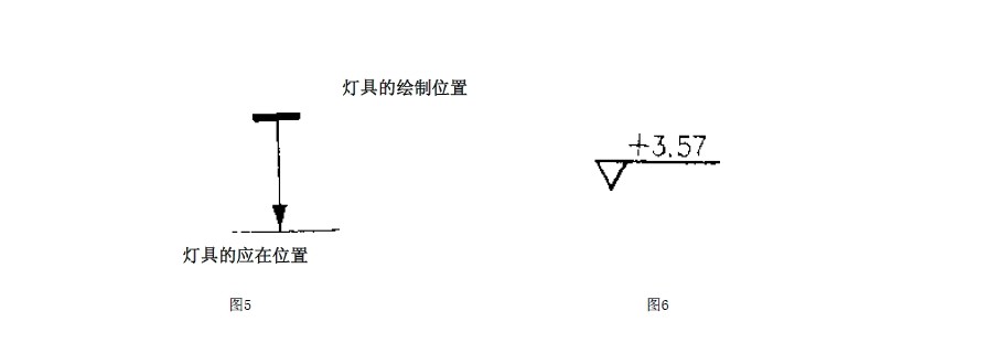

Figure 7
Explanation
1. The luminaire installed on the stage, the mark is 0.00m.
2. Compared with 1, the drawing position is far from the platform, and the plane position is the same as 1, indicating that it is on the upper part of 1, and the height is 7.50m
3. Side light, installed on the flyover, because the flyover height is fixed, you can not mark, and the lamps hanging under the flyover must be marked with height, the drawing position is closer to the central axis.
4. The light on the inside of the platform, the detailed drawing method is to mark the height of each layer.
5. The light on the outside of the platform is a fixed building, and the specific height may not be marked.
5.4.2 Marking of the performance and model of the luminaire If the symbol cannot fully express the performance of the luminaire, it should be marked. The position of the mark is below the symbol. If the position is not allowed, it can be led out with a lead wire and then marked. (See lights 75-80 in Figure 8)
5.4.2.1 Marking of voltage and power
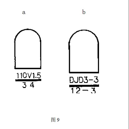
The unit of voltage is volts, no need to mark when using 220V voltage, if other voltages are used, they should be marked and written on the lower left of the symbol. (See Figure 9a)
The unit of power is KW. It is not necessary to write it when labeling, just mark the value, and write it at the lower right of the symbol. (See Figure 9a)
5.4.2.2 If there is a clear requirement for the type of luminaire, it can be marked below the symbol, and the voltage and power labels are omitted. (See Figure 9b)
5.4.2.3 If there are many lamps of the same type, only one lamp can be marked, and the others should be marked with "same X". (× represents the number or direction example see No. 61-68 in Figure 8)
When it is difficult to mark on the picture frame, a separate table may be set up as an attachment to the picture.
5.4.3 Numbering and marking of lamps
The number is the basis for the circuit and operation of the lamp connection, so it must be marked
5.4.3.1 The number of lamps should be based on the line number.
The line number can be determined in the following two ways:
a. All the lines controlled by the dimmer are numbered in sequence, and the direct lines that are not controlled by the dimmer are separately numbered, but the word "straight" must be marked in front, such as "straight-5", that is, the number 5 direct line .
b. According to the number of the lamp position, indicate the abbreviation of the lamp position before the number. For example, the fifth line of front light can be edited as "face-5". When there are multiple lamps on the same line, the line number should be marked first, and then the lamp number of the same line. If there are three lamps on line 5, it should be marked as: "5-1, 5-2, 5- 3".
5.4.3.2 The number is marked as follows:
It is marked below the symbol of the luminaire. If it is confused with the voltage and power labels, they can be separated by a thick solid line. (See Figures 9a, 9b)
5.5 Light pattern
The light layout is generally expressed in an approximate plan view.
The diagram should be able to represent the following:
a. Projection direction of the light beam
b. Projection range of light beam
c. Color of light beam
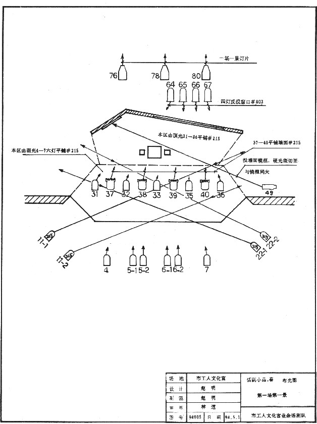
The lighting map can be used together with the lamp bit map, or it can be drawn together with the lamp bit map. In the case of the lamp bit map, the lighting map can only draw the lamps needed in this scene, and generally no longer plot the performance of the lamps. , But the number must be marked. (See Figure 10)
5.5.1 Sagittal representation of the optical axis
An arrow indicates the projection direction of the optical axis in front of the lamp symbol. (See lights 4-7 in Figure 10)
5.5.2 Representation of projection position and range
The following three methods can be adopted as needed:
a. Use text to explain near the lamp position. (See light 49 in Figure 10)
b. Extend the sagittal symbol of the optical axis to the position to be projected with a thin solid line, and draw two arrows, positive and negative, between which is the range of light projection on the stage plane. (See lights 11 and 22 in Figure 10)
c. Frame the projection area with a dotted line. The dotted line is called the projection range line, and the number and description are marked within the range. (For example, see the lamps 31-36 in Example 10)
5.5.3 Color representation
The following methods can be used to express the color of lamps:
a. Use a colored pen to draw the sagittal symbol of the optical axis and the projection range line, where the black line represents white light.
b. It is marked with the number of the color film manufacturer. When marking a single lamp, it can be marked in the lamp symbol. If the symbol is too small, it can be marked near the lamp symbol, but the "#" character number should be added, and it can also be marked. Within the line of light projection or in the text description
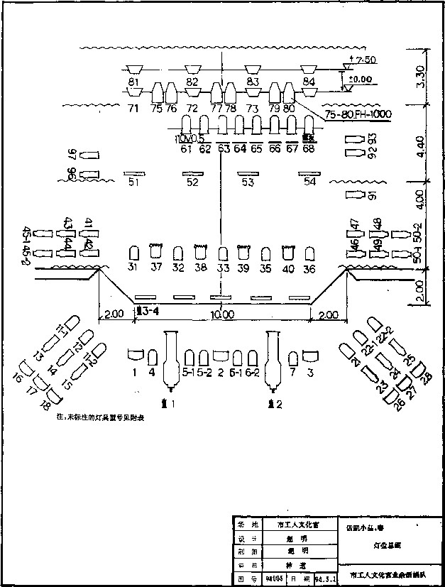
Figure 8
Picture 10
Appendix A
Drawing format
A1 Drawing size
A1.1 When drawing, the format size specified in the table is preferred, and it can be lengthened along the long side if necessary. For A0, A2, and A4 webs, the lengthening should be increased by a multiple of one eighth of the long side of the A0 web; for A1, A3 webs should be increased by a multiple of one quarter of the short side of the A0 web, A0 and The A1 format also allows both sides to be lengthened at the same time.

Appendix B
Font
B1 font
B1.1 The fonts written in the drawings must be correct: the fonts are correct, the strokes are clear, the arrangement is neat, and the intervals are even. Chinese characters should be written in imitated Song style, and simplified characters officially announced by the state should be adopted.
B1.2 The number of the font, that is, the height of the font (in millimeters), is divided into seven types: 20, 14, 10, 7, 5, 3.5, and 2.5*. The width of the font is approximately equal to two-thirds of the font height. Note: The stroke width of numbers and letters is about one tenth of the height of the font.
B1.3 The italic head is inclined to the right and forms an angle of about 75° with the horizontal line.
B1.4 The numbers and letters used as indices, scores, limit deviations, footnotes, etc., generally use a small font.
B2 font example
B2.1 Chinese characters-Long imitation Song type example

B2.2 Examples of Latin letters
Uppercase straight
Capital italics

Lowercase italic
Lower case straight
B2.3 Examples of Greek letters
Capital italics
Lowercase italic
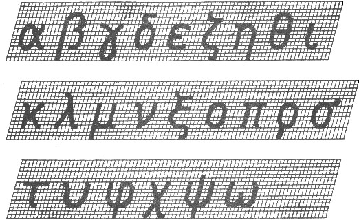
B2.4 Examples of Arabic numerals
Italic

Straight body

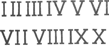
B2.5 Examples of Roman numerals
Italic
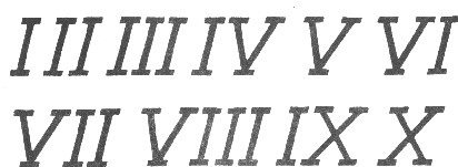
Straight body
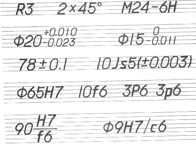
B2.6 Font application examples
Appendix C
Explanation of nouns in theater parts
C1. Theater: a cultural building with a stage for performances, an auditorium for watching performances, and rooms for actors and audiences.
C2. Audience Hall: Halls with fixed seats for watching performances.
C3. Building Block: The floor auditorium on the pool block.
C4. Ikea: The auditorium on the same floor as the stage.
C5. Private room: Auditorium divided into small rooms on the side wall or rear wall of the auditorium.
C6. Stage: The general term for the performance part of the theater, including the main stage, side stage, rear stage, orchestra, lip, ear stage, stage entrance and stage warehouse, etc.
C7. Desk lip: The table mouth line extends out to the countertop of the audience hall.
C8. Ear table; the table surface on both sides of the table lip against the side wall.
C9. Main stage: There is a performance area with lighting set in the entrance of the stage, which is the main performance stage part.
C10. Side platform: Located on both sides of the main platform, the auxiliary area of the main platform is provided for relocating the scenery, temporarily storing props and vehicle platforms.
C11. Rear stage: It is located behind the main stage as a stage part for increasing the second performance area in the depth direction.
C12. The axis of the platform wall: the positioning line of the platform wall marked on the architectural design drawing.
C13. Big curtain line: the projection line of the big curtain on the stage table.
C14. Stage line: refers to the line connecting the pillars or walls on both sides of the stage to the outer skin of the stage. Usually, the stage mechanical positioning is based on this line.
C15. The left and right orientation of the stage: The left and right orientation of the stage is based on the actors standing on the stage and facing the audience hall.
C16. Shed roof: the upper part of the stage is a working layer dedicated to the installation of suspension equipment.
C17. Overpass: working corridor laid along a certain height on the main platform, side platform and rear stage wall.
C18. Fake table opening: The fake table opening is composed of an upper frame and two side frames, which can be moved up and down and left and right along the track, and can be adjusted freely.
C19. Taiwan warehouse: the space below the stage.
C20. Light bridge: It is parallel to the boom and can be raised and lowered. It is a bridge steel frame used for installation, operation and maintenance of light.
C21. Ferry bridge pier: the pick-up board on the overpass, from which you can cross the bridge or light on the fake platform.
C22. Along the curtain: the horizontal bar curtain on the upper part of the main platform.
C23. Side curtain: side curtains on both sides of the main stage.
C24. Frontal curtain: the curtain in front of the big curtain.
C25. Fire curtain: It is a fire separation facility between the auditorium and the stage. It is made of flame-resistant materials and is installed at the entrance of the platform.