The author of this article Mr. Ma Limin, general manager of Guangzhou Squande Lighting Co., Ltd.;
Chief Executive Officer of Squander Lighting China Office;
Mr. Ye Jianhui, Deputy General Manager, Application Design Engineer.
[Abstract] This article introduces the technical characteristics of a series of mobile silicon boxes AT2000 developed by China and Britain and has been produced in Guangzhou, China, and shows the leading design concepts and powerful application functions of my country's new generation of intelligent dimmers.
I. Introduction
The rapid development of microelectronics technology, international advanced digital technology has penetrated into all walks of life; China's accession to the WTO family is just around the corner, and globalization is becoming increasingly fierce. How to introduce foreign advanced technology or design concepts in time, combined with China's local reality, continue to introduce new technologies and new products to meet the needs of the majority of users to develop the digital, network and information technology of film and television stage lighting technology and improve the quality of program production. More and higher demand. This will be a major challenge and opportunity for domestic professional lighting manufacturers in the new century. This article describes the technical characteristics of the newly released AT2000 series mobile silicon box, and shows a new generation of intelligent dimmers with wide application functions and high cost performance.
2.Structure
The AT2000 series intelligent silicon box absorbs the leading technology in the field of lighting control in the world today, adopts optimized design principles and perfect wiring and structural system. The international standard 119-inch box, the chassis and the panel are all formed by die casting and stamping iron plate at one time. The whole adopts the advanced "electrostatic spraying" technology for anti-scratch powder paint spraying treatment, which can withstand impact, abrasion, humidity and high temperature, and maintain beautiful and bright for many years; integrated control button liquid display mode and three-dimensional panel design, The silicon box is elegant in shape and smooth in line, reflecting the ambiguity of fashion and simplicity; the layered design concept of strong and weak electricity is used electrically to avoid the interference of strong electricity to weak electricity, and the electrical strength of the silicon box is maximized and the heat dissipation is maximized. Two ventilation channels are specially designed to make the heat dissipation of the power silicon block and the choke coil, and the low-noise dual fans are used to reduce the temperature of the silicon box, so that the temperature of all components is maintained at an appropriate level. The silicon box does not exceed 450C, and the humidity is between 10 and 90%; the process from the fan to the highest speed is completely controlled by the temperature change inside the silicon box, so as to reduce the noise to the minimum under the operating state, once the silicon box exceeds the temperature After setting, the control circuit will issue an over-temperature warning. If the temperature exceeds 50C, the power of the thyristor control circuit will be automatically turned off. The silicon box provides a variety of mold backplanes to provide users with different options for standard output sockets.
3 .Electronics
The electronic characteristics of modern silicon boxes are mainly reflected in its signal processing, signal output and overload protection capabilities. AT2000 adopts high-performance microprocessor, users can preset linear, S-type and quadratic dimming curves; there are 8 insertion points between each DMX signal level, so that the trigger accuracy is up to 2000, which is provided to the lighting engineer. With excellent precision and smooth dimming, it fundamentally solves the problems of common mobile silicon box false triggering, poor consistency and too narrow dimming range. The dimming range can reach 0% to 100%; at the same time, due to the current domestic The unique three-phase voltage automatic compensation technology greatly improves the consistency of its signal output. When the input voltage changes by ±10%, the output voltage changes by ≤1% to avoid flickering and uneven dimming of the scene lights; digital signal DMX-512 output Using high-speed optocoupler isolation, the isolation voltage reaches 2000V; each output circuit uses a high-speed air switch, which is used to protect the thyristor during short circuit or overload, and can also use the domestic original load intelligent detection circuit to automatically carry out overload load detection, Short circuit automatic sealing protection and alarm signal sending, guiding the lighting engineer to correct errors in a timely manner; adopting high-reliability imported bidirectional thyristors, the silicon-controlled thyristors make full load and output control, and the upper voltage drops to 1V when fully turned on It can withstand the impact of current up to 1200A, which effectively guarantees the working efficiency of the silicon box and enhances the reliability and safety of the silicon box; select the high-efficiency filter choke that meets the requirements of the British BS800, with a rise time of 200US, 300US and 360US Choose the highest efficiency among similar products in the country, effectively reduce the current rise time ratio caused by the non-stop operation of the thyristor, reduce the tungsten wire of the bulb and limit the interference of radio waves on the line and the load conductor; any of the silicon boxes The loop can be set to zero-cross trigger mode, the comparison conversion value can be arbitrarily set in the range of 10% to 90%, or a fixed value can be set for any loop to avoid misoperation.
4.Functions
The combination of modern electronic technology and high-performance micro-processing, the combination of international leading technology and domestic application needs, gives the AT2000 easy-to-use and extremely powerful functions. The control electronics allows the silicon box to be independently dimmable in a single way; the system has powerful output power, 6 kW 6 loops, 3 kW 12 loops, combined flow box 6 kW 24 loops, 3 kW 48 loops for selection; the control circuit allows a single silicon loop The maximum output can be adjusted, and can be set to 0-10% preheat value, which effectively prolongs the service life of the light source of the lamp; the control circuit has a self-test function, the default value is 50%, and 0-100% brightness can be set for the full loop Cycle testing.
The standard status report consists of the following:
A Input voltage per phase
B Digital signal DMX input error
C Silicon box output level (%)
D Silicon box overheat warning
E Overload or short circuit of silicon box;
The load status report consists of the following:
A Load (W)
B Record load deviation
C No load / open circuit breaker
D overload
E Thyristor failure;
The control circuit gives the programmable functions of each silicon box as follows:
A Digital input
B Preset silicon box address code
C Silicon box status report (effective/ineffective)
D Record preset and preset fade time (0~10 seconds)
E Start preset
F Set backup preset (for emergency use when DMX signal input fails)
G Set silicon output level (%)
H Set the maximum output voltage of silicon
I Set dimming curve;
The control circuit supports users to delete, enter and run up to 10 lighting fields, and the storage period is five years. If the input signal is interrupted, the control program can be kept at the last level within the programmable time, and then it will automatically fade into the designated backup field, so that the silicon box can be continuously controlled.
5.Applications
Click MENU on the panel, use ▲▼ keys to select, and then press ENTER to confirm. Through 2×16 bytes LCD recording and display, you can easily operate and control the AT2000 smart silicon box. application:
1. After connecting the power, the LCD of the silicon box control panel is as shown in the figure:
 | AT2000: Model Verson 1.0: Version DMX OK/NO: signal [1]: start address |
2. Click MENU and use the ▲▼ keys to select from the 10 main menus in the following sequence:
(1) Set address setting address code (2) Set cha mode setting silicon circuit mode
(3) Set pre heat function (4) Curve set dimming curve
(5) Channel dim silicon channel brightness setting (6) Channel test channel test
(7) Set voltage setting output voltage (8) Cue scene
(9) Default restores the default value (10) Reporting status report
2.1 Set address (set address code)
In this menu, each silicon box can be assigned a starting address code, and its adjustment range is 1-512.
Set the address code function, the operation is as follows:
1. Press the [Menu] key to enter the function main menu;
2. Select the {Set address} item from the main menu;
3. Press [OK] to enter the address code setting menu;
4. Select the [Up/Down] key to set the starting address code value of the silicon box;
5. Press the [OK] key to confirm the data modification and return to the function main menu; if not, press the [Menu] key to return to the function main menu.
Example: Set the address start code of the silicon box to
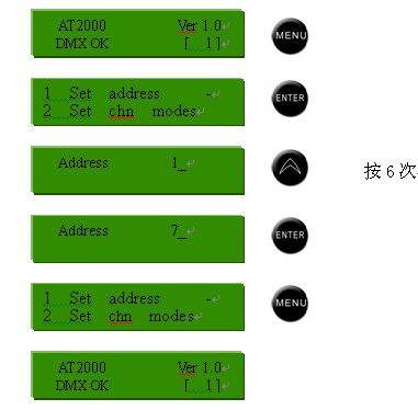
2.2 Set chn mode
In this menu, AT2000 can assign working modes to all or a single independent channel. There are three operating modes that can be selected in this menu (the default setting is EXT mode):
EXT: External control mode, will be controlled by external DMX console.
SW: Switch mode, this channel is only equivalent to the function of a switch, the default value is set to 50%, and the adjustment range is 5%--90%.
FIX: The curing mode will not be controlled by an external console, and will be output directly according to the set value inside the silicon box. The default value is 50%.
Access the function of Set chn mode, the operation is as follows:
1. Press the [Menu] key to enter the function main menu;
2. Select {Set chn mode} and press [OK] to enter the channel setting mode menu; press
[Menu] key to return to the start menu;
3. Press the [Up/Down] key to select different channels;
4. Press the [OK] key to confirm the selection and move the cursor to MODE. Press the [up/down] direction keys to change its channel working mode; when the EXT mode is selected, the channel brightness setting is controlled by the external console (ie The brightness control of the external console has priority);
5. Press ENTER to confirm the selection and move the cursor to the LEVEL option (except in EXT working mode). Press [Up/Down] to assign brightness to the selected channel. Press {OK} to confirm the setting;
6. Repeat operation 3-5, you can set the working mode of other channels;
7. Press MENU to exit to the main menu.
Example: Set the working mode of channel 3 to FIX, and set its brightness to 60%, as shown below.
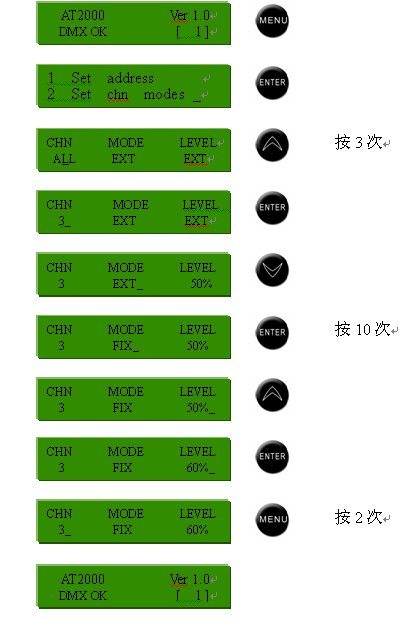
2.3 Set pre heat
In this menu, you can set the preheat (warm) function for all or a single independent channel, preheat
The behavior is based on the intensity of the voltage supplied to the bulb. Before the power supply voltage is supplied, all bulbs are cold and the filament is very fragile, so that when a high-intensity current flows, it is easy to cause the filament to melt. Therefore, the preheating function effectively prolongs the service life of the bulb. The factory default setting of the silicon box preheating is 5, and the brightness adjustment range is 1-10 (this brightness adjustment is set by 256 levels).
To access the Set pre heat function, follow these steps:
1. Press the [Menu] key to enter the function main menu
2. Select the item {Set pre heat} and press [OK] to enter the preheat setting menu, otherwise press [Menu] to return to the initial menu;
3. Press [Up/Down] key to select different channels;
4. Press the [OK] key to confirm the selection and move the cursor to the {level} item;
5. Press [Up/Down] to set the preheat value, press [OK] to confirm the selection;
6. Repeat items 3-5 to set the preheat value for different channels, otherwise press [Menu] to return to the main menu.
Example: Set the preheat value of channel 5 to 8, as shown below.
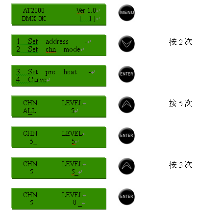
2.4 Curve (Set dimming curve)
In this menu, all channels of the silicon box can be assigned dimming properties, and there are a total of 3 curves for users to choose. (As shown below).
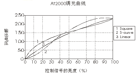
To access the “Curve” function, follow these steps:
1. Press the [Menu] key to enter the function main menu
2. Select the {Curve} item and press the [OK] key to enter the curve setting menu, otherwise press the [Menu] key to cancel
Select to return to the start menu;
3. Press the [Up/Down] key to select the dimmability of the silicon box, and press [OK] to return to the function main menu;
4. Press the [Menu] key to return to the start menu.
Example: Set the dimming curve of the silicon box to Square, the steps are as follows.

2.5 Channel Dim (channel brightness)
In this menu, you can set the brightness for all or a single independent channel, the adjustment range is 0%-100%.
To access the channel brightness setting function, the steps are as follows:
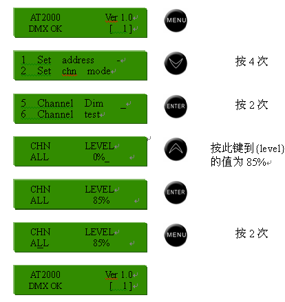
1. Press the [Menu] key to enter the function main menu;
2. Select {Channel Dim}, press [OK] to enter the channel brightness setting menu, otherwise press [Menu] to return to the initial menu;
3. Press [Up/Down] to select the channel, press [OK] to confirm the selection and move the cursor to {level}
options
4. Press [Up/Down] key to set the brightness value of the selected channel, press ENTER key to confirm the above setting, otherwise ‘press [Menu] to cancel the setting;
5. Repeat steps 2-5 to set the brightness of different channels;
6. Press MENU to return to the main menu.
Example: Set the brightness of all channels to
2.6 Channel test
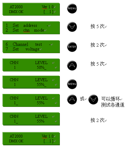
In this dish unit, each channel of the silicon box can be detected. The AT2000 intelligent silicon box can set the brightness of each channel, the adjustment range is 0-100% (the default value is 50%). During the detection process, only each time One channel is detected, and all channels can be tested cyclically (after entering the menu, the first channel enters the blinking state of the test).
To access the channel test function, the steps are as follows:
1. Press the [Menu] key to enter the function main menu;
2. Select {Channel test}, press [OK] to enter the channel test menu, otherwise press [Menu] to return to the initial menu;
3. Press [Up/Down] to cycle through all channels of AT2000 and test them;
4. Press the [OK] key to move the cursor to the {level} selection item (the default value is 50%);
5. Press [Up/Down] to modify the channel brightness test value;
6. Press [OK] to confirm the selection and move the cursor to the {CHN} option;
7. Press [Menu] to return to the function main menu.
Example: Test all the channels of the silicon box, and set the test brightness of the channel to 55%, as shown below.
2.7 Set voltage
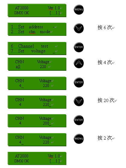
In this menu, you can set a maximum output voltage for all or a single independent channel, the adjustment range is 0-250 volts (the default value is 220 volts).
To access the voltage setting function, the steps are as follows:
1. Press the [Menu] key to enter the function main menu;
2. Select the {Set voltage} item, press [OK] to enter the voltage setting menu, otherwise press [Menu] to return to the initial menu;
3. Press [Up/Down] to change the set channel;
4. Press [OK] to confirm the selection and move the cursor to the {Voltage} item;
5. Press [Up/Down] to set the maximum voltage of the selected channel, press [OK] to confirm the selection; otherwise press [Menu] to cancel;
6. Repeat items 3-5 to set the maximum output voltage of different channels;
7. Press MENU to return to the main menu.
Example: Set the voltage value of channel 4 to 200V, as shown in the figure below.
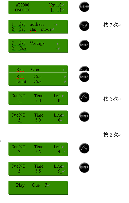
2.8 Cue (scene backup)
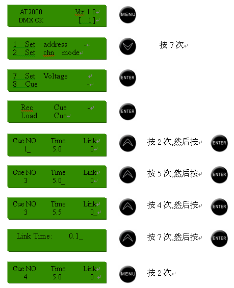
There are two sub-menus in this menu, which are recording scene and deductive scene; firstly, the brightness of the set channel is given by the dimmer or the silicon box itself, and then enter the recording field menu, assigned to a field number, field running time, Connect the field number and the time of the field connection to record the scene (AT2000 silicon box can record up to 10 fields, each field can have up to 12 channels); if you need to import field records, you can import in the import field menu The recorded field numbers you need can be divided into running time and connection field numbers again.
To access the scene backup function, the steps are as follows:
1. Press the [Menu] key to enter the function main menu;
2. Select the {Cue} item and press the [OK] key to enter the scene backup menu, otherwise press the [Menu] key to return to the start menu;
3. The silicon box/lighting console gives certain channels certain brightness;
4. Select the {Rec Cue} item and press the [OK] key to enter the recording field setting menu;
5. Press [Up/Down] and [OK] keys alternately to set the values of {Cue No} {Time}{Link} and {Link Time} respectively; otherwise press [Menu] key to return to the previous menu;
6. Repeat steps 4-5 to record different fields;
7. You can also select the {Play Cue} item to perform the recorded scene.
Example: Record CUE3 when the brightness of all channels is 45% and set the field time to 5.5 seconds and the connection time to field 4 to 0.8 seconds.
In the presence record, there are several options that should be explained:
1. In the {Cue No} option, the default value is 1, and the setting range is 1-10;
2. In the {Time} option, its default value is 5.0, and the setting range is 0.1-9.9;
3. In the {Link} option, its default value is 5.0, and the setting range is 0.1-9.9;
4. In the {link Time} option, its default value is 0.1, and the setting range is 0.1-9.9;
5. After selecting the {Play Cue} item, press [OK] to enter the demo menu and select the field number (the selected field must be something
(Recorded before), you can modify the operation time of the field and the connected field number in real time, and then you can run the field;
After the field operation task is completed, you can press the [Menu] key twice to close the running field and return to the previous menu.
Example: call field 3, and change its connection field 5;
2.9 Default
In this menu, all parameters of the silicon box can be restored to the factory default values.
Access the menu function of restoring default value, the steps are as follows:
1. Press the [Menu] key to enter the function main menu;
2. Select the {Defaults} item and press [OK] to enter the default value recovery menu;

3. Press the [OK] key to restore all settings to the default values and return to the function main menu; press the [Menu] key to keep the existing settings and return to the function main menu.
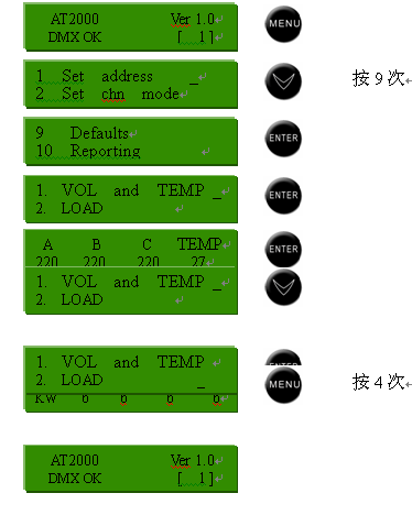
2.10 Reporting
In this menu, you can view the maximum voltage value and internal temperature of each input of the silicon box and the load of each output circuit.
To access the report function, the steps are as follows:
1. Press the [Menu] key to enter the function main menu;
2. Select {Reporting} and press [OK] to enter the report menu;
3. Select {VOL and TEMP} to view the maximum input voltage of each channel of the silicon box and the internal temperature of the silicon box;
4. Select {LOAD} to view the load of each output loop;
Example: Check the three-phase input voltage and internal temperature of the silicon box:
3. The application of various commonly used menu functions are briefly described as follows:
(1) Preset address: Enter the "Set address" main menu, you can define the starting address of each silicon box, the adjustment range is 1 ~ 512, you can control dozens of parallel silicon boxes.
(2) On-site dimming: Enter the "Set cha mode" main menu, you can set the following for each thyristor circuit:
① ЕXT: The silicon circuit is controlled by an external dimmer;
② FIX: The silicon circuit is controlled by the brightness adjustment inside the silicon box;
③ SW: The preset of silicon circuit is equivalent to a switch function;
(3) Preheating setting: AT2000's main preheating menu can set the preheating (warming) function for each independent silicon output circuit, and adjust the brightness to 0%~10%, which can effectively prolong the service life of the lamp.
(4) Dimming curve: AT2000 has 4 dimming curves to set the silicon circuit.
(5) Brightness setting: enter the "Channel Dim" main menu, you can adjust the brightness of each independent silicon circuit, the brightness can also be adjusted by an external console.
(6) Cyclic test: select a silicon circuit, preset its brightness value, and then cycle through each silicon circuit test.
(7) Output setting: Use this menu to set the output voltage for each silicon circuit individually, the adjustment range is 0 ~ 250V.
(8) Scene backup: There are two submenus in the scene backup main menu, which are the recording field and the import field. The dimming station first gives the brightness of the silicon circuit, and then enters the recording submenu to record the field. Import the fields you need in the Import submenu.
Six conclusion
Due to the use of advanced design concepts and unique technical methods, high-standard selection of some key imported components, "quality" production management and quality control, AT2000 deepens digital technology in domestic mobile silicon boxes and broadens application performance, undoubtedly bringing new Breakthrough. I believe that this new generation of intelligent dimmer with high cost performance will add luster to the domestic and foreign film and television stage.